
Manufacturing Facility Fiber Optic Ring Installation — Terrell, TX
Five hubs, one closed ring, redundant backbone — completed inside an operating plant with active forklift traffic.
Project Overview
Cabling in DFW installed approximately 1,500 feet of client-provided 24-strand singlemode fiber at a manufacturing facility in Terrell, Texas, completing the work in July 2026. The fiber was routed in a closed loop that connects the facility server room to four network hubs and then returns to the server room, forming a redundant fiber ring across the plant.
The facility runs production across a large footprint, with network hubs distributed through the building rather than concentrated in one area. The physical path carrying traffic between the server room and those hubs matters as much as the equipment on either end of it.
The requirement was to establish a backbone that does not depend on a single physical fiber path. Instead of running fiber out to the last hub and stopping there, the route was carried back to the server room to close the loop. Cabling in DFW installed the fiber along the existing fiber ring pathway, core drilled through concrete walls, made the cabinet penetrations needed to route cable into equipment, and fusion spliced all 240 strands at five termination locations over several days. All of this took place inside an operating plant, with forklift traffic moving through the building and limited overhead clearance along parts of the route.
The Client’s Infrastructure Need
The challenge was not simply running fiber between two points. The facility required a closed-loop backbone connecting five network locations while accommodating the physical constraints of an operating manufacturing environment.
The scope centered on four requirements:
- Connect one server room with four network hubs distributed across the facility
- Build redundancy into the physical backbone rather than relying on a single fiber path
- Maintain connectivity to every connected location if one point in the ring experiences a break
- Work within the facility existing fiber ring pathway and around active production
That last point shapes everything else. An existing pathway brings its own conditions: where the cable can be supported, where it has to cross a concrete wall, and how much overhead room is actually available once you are on a lift looking at it. The client also supplied the fiber, so the route had to be planned against a fixed quantity of 24-strand singlemode cable.
Project Challenges
Active Manufacturing Environment
The plant was running while the fiber went in. Forklifts were moving through the building on their normal routes, so every ladder placement, lift position, and staging area had to account for vehicles that had priority in those aisles. That changes the pace of the work. Sections of a cable pull that would take an hour in an empty building get broken into shorter windows, and the crew has to be able to stop, clear the area, and pick the run back up without leaving cable exposed or unsupported.
Tight Overhead Clearances
Parts of the route had limited overhead space. In an industrial building the overhead is already busy with electrical, mechanical, air lines, lighting, and existing low-voltage cable, so tight clearance leaves fewer options for where the fiber can sit and how it is supported.
Bend radius is the practical concern. Singlemode fiber does not tolerate being pulled hard around a corner or crushed against a support, and a restricted route gives you less room to make gradual transitions. Planning those transitions before the pull is faster than discovering them during it.
Concrete Walls and Cabinet Penetrations
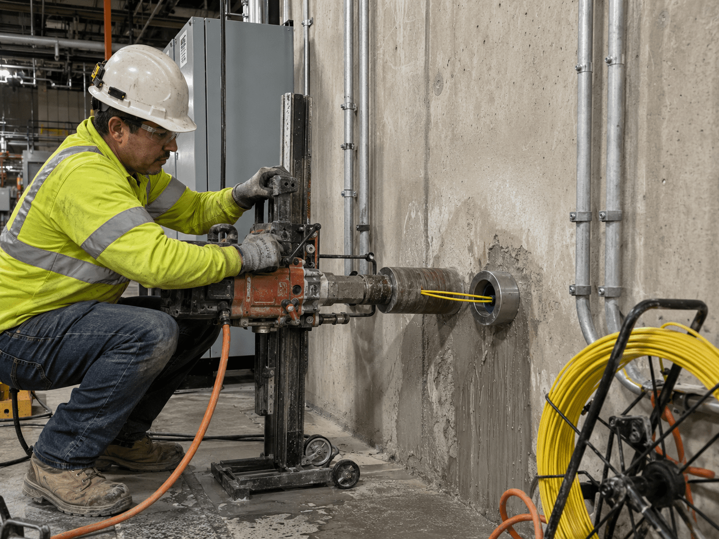
The route crossed concrete walls, so core drilling was required to create pathways between sections of the building. Core drilling in an occupied facility is a planned activity: the location has to be chosen with an understanding of what sits on both sides of the wall, and the work coordinated with the areas around it.
Cabinet penetrations were the other access requirement. Fiber has to enter enclosures cleanly, with enough slack to be handled during termination and enough protection at the entry point.
Multiple Fiber Termination Locations
A 24-strand fiber run crossing five locations is an organizational problem as much as a technical one. Strand identity has to be tracked consistently from the server room through Hub 5, Hub 4, Hub 2, and Hub 3, and back again. An error at one enclosure creates confusion at every location downstream, and it usually surfaces later during troubleshooting.
Redundant Closed-Loop Design
Running fiber out to four hubs in a line is a shorter job than running it out and bringing it back. The return leg to the server room is what makes the design a ring, and it is the reason the facility gets redundancy out of the installation.
Fiber Optic Installation Solution
Cabling in DFW installed the client-provided 24-strand singlemode fiber along the existing fiber ring pathway, following the route Server Room to Hub 5 to Hub 4 to Hub 2 to Hub 3 and back to the Server Room. The scope covered the physical installation, the concrete and cabinet penetrations required to complete the pathway, fusion splicing at all five termination locations, and a walkthrough of the splicing equipment and procedure with the client on-site contractor.
Approximately 1,500 feet of fiber was placed across the five connected locations, and the work was completed over several days inside the operating facility.
Installation Process
Follow the Existing Fiber Ring Pathway
The facility already had a fiber ring pathway, and the installation followed it: Server Room to Hub 5 to Hub 4 to Hub 2 to Hub 3 and back to the Server Room. Walking that route first establishes where the cable can be supported, where penetrations are needed, and where clearance is going to be tight, which is what makes the actual pull predictable.
Route Approximately 1,500 Feet of Singlemode Fiber
The client supplied the 24-strand singlemode fiber, which is 12 pairs. Roughly 1,500 feet was routed across the full loop. Because the fiber was client-provided, the route had to be planned against the material on hand, with slack allocated where it was needed at the enclosures rather than consumed early in the run.
Create Required Penetrations
Core drilling through concrete walls opened the pathways between sections of the facility, and cabinet penetrations provided the entry points into equipment. Between those points, the cable had to be routed around the physical obstacles present in an industrial building, including existing overhead infrastructure and the areas where forklift traffic could not be disrupted.
Complete Fiber Fusion Splicing
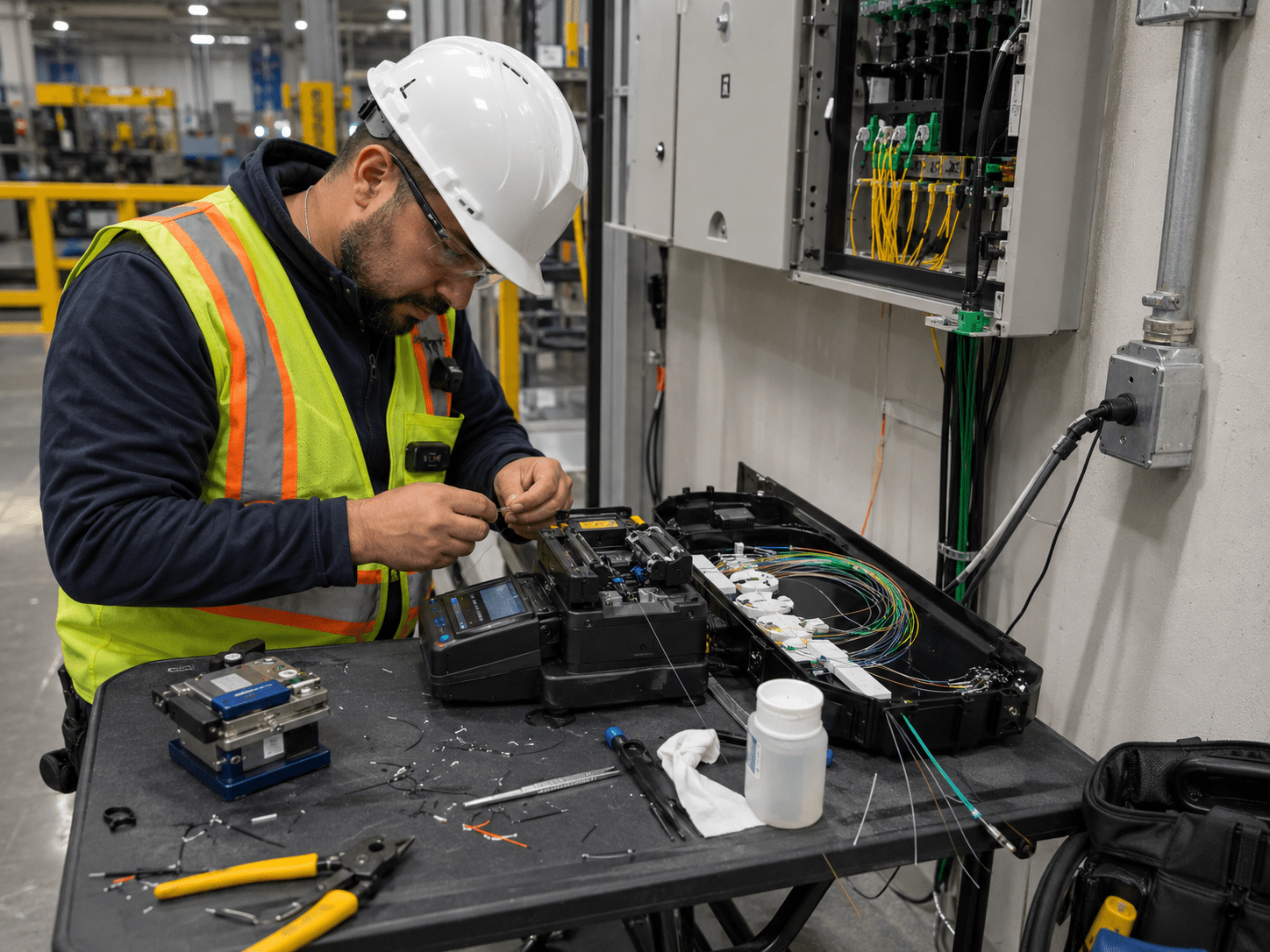
All 240 strands were fusion spliced across the five termination points. Fusion splicing joins two fibers by aligning the glass cores and fusing them with an electric arc, creating a continuous optical path through the joint.
Across 240 strands at five locations, the job comes down to consistent, repeatable technique rather than one difficult splice.
Complete the Closed Fiber Ring
The final leg carried the fiber pathway from Hub 3 back to the server room, closing the loop. This is the segment that turns a chain of hubs into a ring and delivers the physical redundancy the project was built around.
Provide On-Site Contractor Training
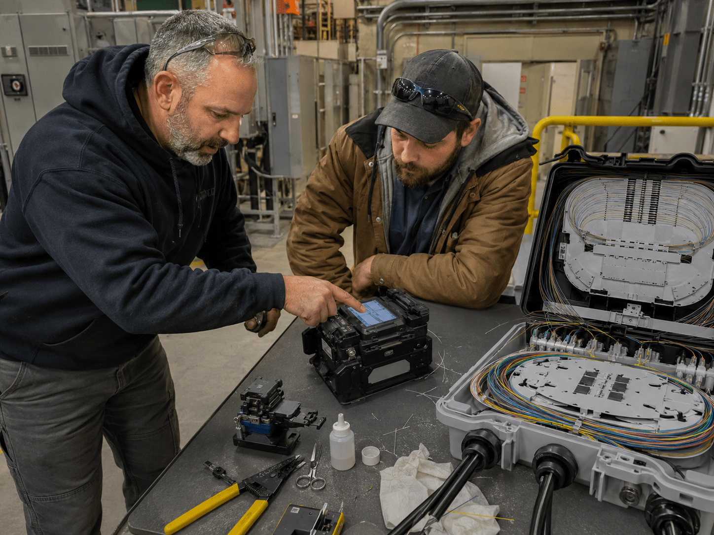
The client on-site contractor was given a walkthrough of the fusion splicing equipment and the basic splicing procedure. The goal was familiarity with the system that was just installed, so the client has an on-site resource who has seen how the terminations were made.
Understanding the Redundant Fiber Ring
What is a fiber optic ring?
A fiber optic ring is a cabling layout where the fiber pathway leaves a starting point, passes through each connected location, and returns to where it started, so every location on the loop has more than one physical direction back to the origin point. Compare that to a straight run: if fiber goes from a server room out to four hubs in sequence and stops at the last one, every hub depends on the segments in front of it, and a cut in the first segment affects everything past it.
On this project, the installed route connected Server Room to Hub 5 to Hub 4 to Hub 2 to Hub 3 and back to the Server Room. That closed-loop layout provided the physical redundancy the client required.
Fusion Splicing Scope
The cable was 24-strand singlemode fiber, and every strand had to be terminated at each of the five locations on the ring, bringing the total to 240 strands fusion spliced.
The process for a single strand looks like this:
- The buffer coating is stripped back to expose the bare glass fiber
- The bare fiber is cleaned so no residue remains on the surface
- The fiber is cleaved to produce a flat, square end face
- Two prepared fibers are aligned in the splicer and fused with an electric arc
- The completed splice is protected and secured inside the enclosure
Each of those steps happens 240 times on a project like this one, which is why organization matters. Splice trays have to be laid out so future work is possible without disturbing completed splices, and slack has to be managed so nothing sits under tension. A well organized termination is easier to troubleshoot two years from now, and that is worth more to a facility than shaving time off the install.
Working Inside an Active Manufacturing Facility
Commercial fiber work in a manufacturing plant is a different job from cabling an office suite, and the difference shows up in the planning more than in the splicing. The conditions on this project included:
- Forklift traffic: vehicles move through the building on established routes, and cabling work has to be staged around them
- Production environment: the facility is operating, so access to areas is scheduled rather than assumed
- Tight overhead space: limited clearance restricts where cable can run and how transitions are made
- Concrete walls: crossing between sections requires core drilling rather than a simple pass-through
- Distributed network hubs: the four hubs sit at different points in the building, so the route covers real distance across the plant
- Existing pathways: the fiber ring pathway was already established, and the installation had to work within it
Each of these adds coordination to the schedule. This is the part of a commercial fiber project that experience changes most, because the splicing technique is the same everywhere and the building never is.
Contractor Training and Project Handoff
The scope on this project included more than installing and terminating cable. Before the crew left, the client on-site contractor was shown how the fusion splicing equipment is used and walked through the fiber splicing procedure.
That handoff gives the client maintenance resource direct familiarity with the fiber system in the building: how the terminations were made and what the process looks like in practice. It is a walkthrough rather than a certification program, and the value is practical. Someone on site has seen the work rather than only inheriting the result of it.
Results
The completed fiber ring created a redundant backbone between the server room and all four network hubs, so a single break in the ring does not take down connectivity to any part of the facility.
The completed physical infrastructure includes:
Approximately 1,500 ft of client-provided singlemode fiber installed
Five facility locations connected: server room plus Hubs 2, 3, 4, and 5
Closed-loop fiber pathway completed back to the server room
240 strands fusion spliced across five termination locations
Required concrete core drilling and cabinet penetrations completed
On-site contractor familiarized with the splicing equipment and procedure
What This Project Demonstrates
For businesses in the Dallas-Fort Worth area evaluating a fiber project, this job covers a set of capabilities that come up regularly in commercial and industrial work:
Multi-location fiber backbones connecting a server room to several network hubs or IDFs
Singlemode fiber installation across long runs inside a single facility
Redundant pathway design, including closed-loop ring configurations
High-count fusion splicing across multiple termination locations
Core drilling, cabinet penetrations, and complex commercial cable routing
Fiber installation in manufacturing plants, warehouses, and large commercial facilities
Working within existing pathways in an operating environment
Who Might Need a Similar Installation
A backbone like this one tends to fit facilities where the network is spread across a large footprint and connectivity between closets matters to daily operations:
- Manufacturing plants with network equipment distributed across the production floor
- Warehouses and distribution facilities covering large square footage
- Large office campuses with multiple network closets
- Multi-building commercial properties
- Data-intensive facilities where backbone capacity is a planning factor
- Any facility with several hubs or IDFs feeding back to a central server room
Not every building needs a fiber ring. The correct topology depends on the building layout, network requirements, distance, redundancy goals, and existing infrastructure. A facility with one closet next to the server room has different needs than a plant with four hubs spread across it, and the right answer starts with looking at the site.
Have a fiber project in DFW or beyond?
We’ll visit your site, scope the work, and give you a clear plan — at no cost.